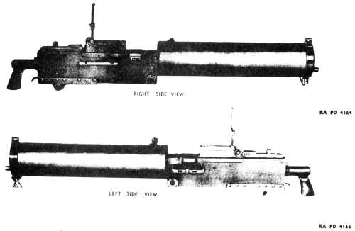
Figure 1- Browning Machine Gun, Cal .30, M1917A1
a. This manual is published for the information and guidance of Ordnancemaintenance personnel. It contains detailed instructions for inspection,disassembly, assembly, maintenance, and repair of the followingmateriel.
GUN, machine, cal. .30, Browning, M1917A1, water-cooled.
GUN,machine, cat .30, Browning, M1919A4, fixed and flexible.
GUN, machine, cal.30, Browning, M1919A5. fixed.
GUN, machine, cat .30, Browning, M1919A6,flexible.
GUN, machine cat 30, Browning, MZ, aircraft, fixed andflexible.
MOUNT, tripod, machine gun, cal .30 M2.
MOUNT, tripod, machinegun, cal 30 M1917A1
MACHINE, belt filling, Browning, M1918.
b. These instructions are supplementary to those in the Field Manuals andTechnical Manuals prepared for the using arms. This manual does not containinformation which is intended primarily for the using arm, since suchinformation is available to Ordnance main- tenance personnel in lOO-series TM'sor FM's.
c. This manual diflers from TM 9-1205, dated 4 April 1942, in the followingrespects:
(1) The following obsolete guns have been omitted;
Browning machine gun,M1917, water-cooled.
Browning machine gun, M1918, aircraft fired andflexible.
Browning machine gun, M1919, aircraft, fixed andflexible.
Browning machine gun, M1919AZ, fixed and flexible.
Browningmachine gun, YZ, heavy barrel, fixed and flexible (never standardized).
U.S.machine gun, cat .22, MI,
(2) The following guns and mounts have been added:
Browning machine gun,M1919A5, fixed.
Browning machine gun, M1919A6, flexible.
Tripod mount cal,,30, MZ.
Tripod mount eel .30, M1917A1.
(3) Trainers an not included in this manual as this information may he foundin pertinent Field Manuals.
(4) information has been added on the shuttle-type belt filling machine.
(5) Sections have been added on mechanical functioning, disassembly andassembly, and cleaning and lubrication.
a. The cal. .30 Browning machine gurls (all types) as listed above are web orlink belt feed, recoil-operated, water- or air-cooled. The functional mechanismsof the guns covered by this manual are relatively identical. This type weapon,with its various models, is designed to fire at materiel, aircraft, personnel,or vehicles; to fire from tripod, bipod, antiaircraft mount or various vehiclemounts or aircraft and can be adapted to either fixed or flexible mountings.These guns, with the exception of the M2 Aircraft Gun have single- feed boltsand are fed from the left side; the M2 Aircraft Gun has an alternate feed bolt,and can be fed from the left or right side when so assembled.
b. The cal. .30 Machine Gun Tripod Mount MZ (fig. 8) isa portable, folding tripod and is intended for ground fire It mounts a cal. 30M1919A4 Flexible Gun.
c. The cal. .30 Machine Gun Tripod Mount M1917A1 (fig. 9) isa portable, folding tripod. The mount is intended for ground fire but can beused up to a limited angle for antiaircraft fire. it mounts a cat .30 M1917A1Gun.
a, Browning Machine Gun, Cat .30, M1917A1 (fig. 1).This gun is a water-cooled gun and is designed to provide for quick mount- ingand dismounting The elevating stem of the elevating mechanism is retained in avertical position and keyed to prevent rotation. The principal features of theM1917A1 Gun are as follows:
(1) The bottom plate D-35392 includes all the pieces of the stirrup plus themounting bracket
(2) A new design of belt feed lever and pivot of the type used in the cat 30Browning Machine Gun M1919A4, was made because of the relocating of theammunition chest on the ground rather than on the tripod. This relocatingresulted in a greater increase in load to be hfted by the feeding mechanism ofthe gun.
(3) An improved latch assembly is used with a new type of spring,
(4) Sights are graduated for the use of either M1 ball ammunition or M2ammunition.
(5) Guns modified at a later date are equipped with cover catch assemblies toretain the cover in a fixed position, whenever it is opened.
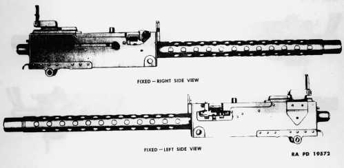
Figure 2- Browning Machine Gun, Cal .30, M1919A4, Fixed
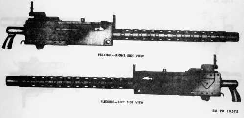
Figure 3- Browning Machine Gun, Cal .30, M1919A4, Flexible
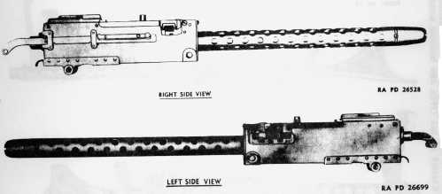
Figure 4- Browning Machine Gun, Cal .30, M1919A5, Fixed
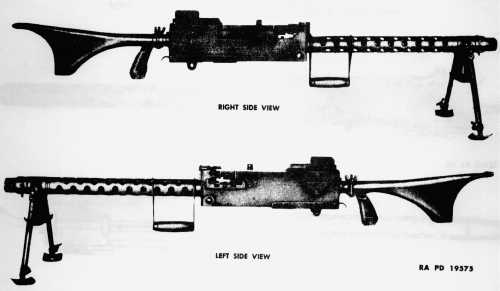
Figure 5- Browning Machine Gun, Cal .30, M1917A6, Flexible
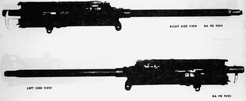
Figure 6- Browning Machine Gun, Cal .30, M2, Aircraft, Fixed
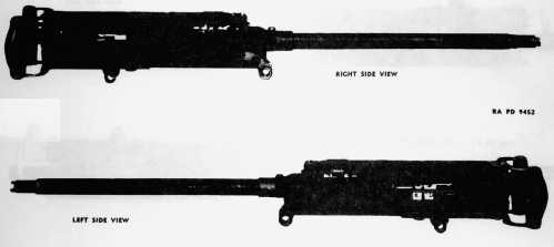
Figure 7- Browning Machine Gun, Cal .30, M2, Aircraft, Flexible
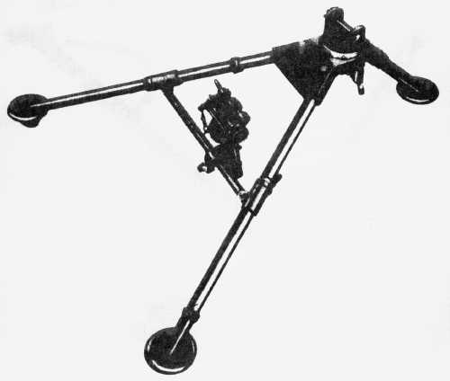
Figure 8- Machine Gun Tripod Mount, Cal .30, M2
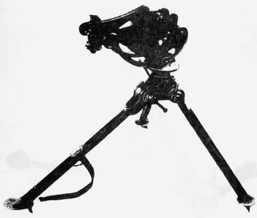
Figure 9- Machine Gun Tripod Mount, Cal .30, M1917A1
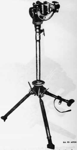
Figure10 - Gun Elevator, Cal .30, Assembled to Machine Gun Tripod Mount, Cal .30,M1917A1
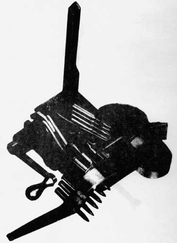
Figure11 - Browning Belt Filling Machine, Cal .30, M1918 - Needle Type Showing Belt inPosition for Loading.
(6) A tension spring is in the rear sight assembly for the purpose of dampingthe vibration of the sight.
(7) Later modifications brought about the following additional changes:
(a) A steel end cap in place of the bronze end caps currently used.
(b) A steel trunnion block in place of the currently used bronze trunnionblock.
NOTE: Both the steel trunnion block and steel end cap are inter- changeablewith the bronze parts formerly used.
(c) An improved steam tube assembly of the type used in the cat .50,water-cooled Browning Machine Gun M2.
(d) A new cartridge bunter plate of the type used in the cat 30 BrowningMachine Gun M1919A4 is of cylindrical rather then of flat type
(e) An improved noncorrosive muzzle gland assembly in the end cap isused.
(f) A recoil plate in the bolt which is similar to those now used in the cat30 Browning Machine Gun Ma and the cal 50 M2.
(g) A rear sight graduated for M2 bah ammunition.
(h) A cover catch assembly is assembled to an guns.
h. Browning Machine Gun Cal. .30, M19L9A4 (fig. 2 and3).
(1) The M1919A4 Gun is an air-cooled gun incorporating the followingfeatures:
(a) The barrel is 24 inches in length. The bores of the rear barrel bearingand front barrel bearing are the same A separate front barrel bearing plug issupplied for both M1 and MZ ammunition.
(b) The barrel jacket is 19.OS inches in length.
(c) The belt feed lever group assembly provides for the assembly anddisassembly of the belt feed lever from the top of the cover The belt feed leverpivot bushing forms the bearing for the belt feed lever pivot and is locked tothe cover by the bushing nut A cotter pin is provided to retain the pivot in theassembled position.
(d) The rear sight a mounted on the cover latch and is equipped with aregraduated leaf for a sight radius of 14 inches, a rear sight slide mil scale,and a windage scale The sight is hinged so as to fold for convenientpacking.
(e) The front sight is rigid and assembled to the trunnion block of thegun,
(f) A number of these guns are modified by the addition of a cover catchassembly.
(2) The M1919A4 of later and present manufacture is identical with those ofprevious manufacture except for the following changes:
(a) The flexible back plate assembly has been modified by replacing thetapered buffer plug, buffer ring, and buffer fil'ler with an assembly consistingof a buffer plug, buffer ring, and buffer disks. This construction elirninates"freezing" of the ring and plug, which condition retards the action of thebuffer spring
(b) The bottom plate is of a new design which eliminates the separate stirrupelevating bracket and bottom plate of the previous models by having the threecomponents integral with the precent bottom plate. The bottom plate is rivetedto the receiver and provided with a recess to locate the machine gun in the packhanger,
(c) The belt feed lever is held in position by a cotter pin in place of aspring cap. The pivot fits tightly in the belt feed lever as its bearing is inthe bushing The belt feed lever pivot is held in place by a nut assemblyconsisting of a belt feed lever pivot nut screw and lock washer In a previousmddification, the old belt feed lever pivot pin and belt feed lever bushing werealso used for the group assembly.
(d) The latch handle is riveted to the latch to facilitate the manual releaseof the cover latch. The handle replaces the latch knob used in previous models.Latest revision has made the latch handle an integral part of the latch.
(e) The rear sight base is mounted on a bracket which is fastened to the leftside plate of the receiver. The graduations for range have been increased.
(f) The front sight is hinged to permit folding for convenience in packingthe gun.
(g) The trunnion block is equipped with cartridge bunter plate to resist wearat that point
(h) The cover group has been modified so that the belt feed lever action willbe more free.
(i) The driving spring load was decreased from 18 pounds to 14 pounds toinsure sufficient recoil of the bolt so that the next round might be fed.
(j) The flexible back plate component parts were changed to prevent"freezing" in the buffer tube
(k) The extractor was redesigned so as to insure proper cartridgeextraction.
(1) The back plate was further modified by having plastic grips replace theformer aluminum grips. (par. 3 b (3) (c)).
(m) The fixed back plate was redesigned so that the buffer tube ishorizontal.
(3) The latest manufacture includes the above modifications plus theadditional ones which follow:
(a) The casing assembly has been rnodified 90 that the barrel jacket is nowsoldered to the casi.ng. NOTE: Since 1AB modification, barrel jackets are not tobe disassembled in field stripping.
(b) The latch stop screw has been eliminated as a result of the latch stopbecoming an integral part of the back plate.
(c) The back plate group has been further modified by making the grip anintegral part of the back plate and of cast steel.
(d) The front barrel bearing has been rnodified so as to con~~- date theformer front barrel bearing plug lock band and plug, and has made them anIntegral part of the new barrel bearing.
(e) The bolt latch and bolt latch rivet have been eliminated completely.
(f) The cover has been redesigned so as to include the cover plate and coverextractor cam as integral parts of the cover.
(g) The back plate has been further modified so that it now resembles thealuminum-type grip, and has the extensions on the bottom of the grip which areadaptable to hold the grip to its mount when being moved.
(h) The trigger has been modified so that a lobe has been added to the searend of the trigger to facilitate better functioning.
c. Browning Machine Gun Cal. .30, M1919AS (fig. 4).This gun is identical with the M1919A4, but has been modified so as to functionin only fixed mountings where space is li.mited. It differs from the M1919A4 Gunas follows:
(1) It has no front or rear sight group.
(2) A retracting slide is assembled to the right side of the gun tocomplement fixed operation.
(3) A cover detent group is assembled to the left side of the gun in place ofthe cover catch group on the right side of the M1919A4 Gun.
d. Browning Machine Gun, Cal. .30, M1919A6 (fig. 5).This gun is basically the same as the M1919A4 Gun of latest design as describedin paragraph 3 h, and is adaptable for mounting on either tripod or bipod mountIt was designed to be used solely as a light flexible weapon. When mounted onbipod, if necessary, the bipod legs can be folded to the rear, and the bipodrest legs used as a front support This gun differs from the M1919A4 Gun asfollows:
(1) The front barrel bearing has been modified so as to facilitate mountingof the bipod.
(2) A bipod assembly is mounted to the front barrel bearing.
(3) Recent guns have still a different front barrel bearing with a boostercap and clip assembled.
(4) The barrel jacket has been modified to adapt the use of the new frontbarrel bearing
(5) The barrel has been modified by making it lighter end adaptable to thenew bearing
(6) The barrel plunger spring is hghter, making bolt retracting easier
(7) A carrying handle has been added to the barrel jacket to facihtate thehandling of a hot gun.
(8) The cover latch has been modified, making it easier to un- latch thecover
(9) A metal shoulder stock is mounted to the back plate to facihtate flexiblefiring of the gun.
e. Browning Machine Gun, Cat .30, M2, Aircraft (fig. 6 and7). Thisgun is recoil-operated, belt-fed, and air-cooled, and has chracteristicsprimarily identical with those models previously described. A metallic link,disintegrating belt a used in an firing. This gun is designed for both fixed andflexible use and has an alternate feed bolt by which, by repositioning some ofthe component parts, the gun may be fed from either the right or left side asdesired. Fundamentally the fixed and flexible guns are the same except for thoseparts which convert the gun into either fixed or flexible type.
(1) FIXED GUN. The fixed gun is installed in the fuselage of the aircraftimmediately forward of the pilot, or mounted within the wings An operating slideconnects with the bolt by means of the bolt stud, and a cable may be attached topermit remote control When operated by hand, the operating slide retracts thebreech mechanism for loading unloading and reduction of stoppages in firing Theslide can be fully retracted and retained in this position by turning the handleto the right or left. Other characteristics are:
(a) The fixed gun is normally assembled with a back plate having a horizontalbuffer, although guns of early manufacture came equipped with a vertical bufferwhere hmited mounting space necessitated this design for proper adaptation. Theback plate in either case doer not have spade grips.
(b) The fixed gun, when mounted adjacent to the airplane engine, is firedthrough the plane of propeller rotation by a synchronizing system which timesthe fire in relation to the rotating propeller blader This mechanism consists ofa synchronizer impulse generator unit which is an integral part of the airplaneengine, a trigger motor mounted to the gun casing and an electrical control unitor solenoid. The impulse generator is connected with the trigger motor by asemi- flexible tube and wire assembly, and the firing of the gun is controlledby a switch. The gun is fired by a trigger motor, timed to the revolu- tion ofthe propeller.
(c) The fire of wing-mounted guns is controlled by solenoid and operated by aswitch usually mounted on a control stick of the airplane. These guns delivercomplete automatic fire.
(2) FLEXI8LE GUN. The flexible gun is installed in the fuselage and hasaretracting slide normally located on the right side of the gun. This connectswith the bolt by means of the retracting slide bolt stud. This adaptation of theretracting slide allows for fire and stoppage control by hand. The retractingslide handle remains stationary and forward while the weapon is firing, thuseliminating ah moving parts outside the gun casing. The flexible gun, inaddition to the retracting slide, is provided with a back plate havinghorizontal buffer, double spade grips, and a hand trigger. This gun so equippeddelivers full automatic fire.
f. Machine Gun Tripod Mount, Cal. .30 M2 (fig.8).
(1) This a a tripod mount incorporating the following featurea It consists ofthree tubular steel legs articulating in a tripod head. the two rear legs beingloined and additionally supported by a trav- ersing bar forming a simple A-trussand serving as a rear support for the mounted gun. The tripod head furnishes afront support for the mounted gun, it being in turn supported by the short frontleg,
(2) Incorporated In the tnpod head is a bronze plntle bushing, mating withthe tapered steel pintle attached to the receiver of the gun. The pintle issecured in its union with the bushing by engagement of the pintle lock groupassembly of the tripod in its corresponding annular groove of the pintle. Thepintle lock group assembly is spring-actuated and is seated in its housing onthe lower right surface of the tripod head.
(3) The traversing bar provides a rear support for the mounted gun, theelevating mechanism sleeve mating with the bar, An addi- tional device formeasuring or establishing horizontal angles is incorporated in the scaleengraved on the traversing bar. This scale is divided into 100-mil majordivisions, and 5-mil minor subdivisions, It has a range of 450 mils to the rightand 425 mils left of zero graduation.
(4) The traversing bar articulates in sliding sleeve devices at each end, thesleeves moving along the rear legs in mounting and dismounting the tripod. Thetraversing bat sleeve latch, mounted on the right leg, secures the traversingbar in its proper position when the tripod is mounted.
g. Machine Gun Tripo(l Mount, Gal, .30, M1917A1 (fig.9).
(1) This mount has as a central member a socket with three projecting lugs.Attached to the socket are three legs which may be clamped independently invarious positions,
(2) The cradle pintle fits into the socket and turns in it 89 a pivot Thecradle pintle clamping screw assembly prevents the pinde from being pulled outof the socket and controls the ease of rotation of the pintle, The traversingdial seated on top of the socket may be rotated in its seat The traversing dialmay be locked in any position by means of the traversing dial knob.
(3) The cradle is assembled to the top of the pintle by means of the trunnionstuds which are threaded into seatings in the pintle yoker The vertical movementof the cradle around this yoke may be adjusted or fixed at a desired point bymeans of the cradle c~amp- ing handle. In the forward end of the cradle isassembled the pintle lock group assembly equipped with a quick release latch.The ele- vating and traversing mechanism is housed in the rear end of the rightand left side plates of the cradle. Elevating and traversing screws actuated byfiandwheels provide mechanical means for manipulation in single-milincrements.
(4) An accessory to this mount is the cat 30 gun elevator (fig. 10).This is approximately 31 inches long and is composed principally of a pintle,tube, and cocket It is used in conjunction with the M1917A1 Mount forantiaircraft fire. This elevator is used by removing the cradle assembly fromthe tripod and inserting the pintle end of the elevator into the socket of thetripod. The cradle assembly is then insetted in the socket end of theelevator.
a. In order to provide for more clarity of understanding, the data of each ofthe guns and mounts described in this manual will be handled separately asfollows:
. | (1) BROWNING MACHINE GUN, CAL 30, M1917A1 |
| Weight of gun with water | 41.00 Ib |
| Weight of gun without water | 32.6 Ib |
| Length (over-all) | 38.64 in. |
| Weight of recoding parts | 7.35 Ib |
| Weight of barrel | 3 lb |
| Length of barrel | lL3.9 in. |
| Length of rifling | 21,38 in. (71 cat) |
| Rifling: | - |
| Number of grooves | 4 |
| Right-hand twist | One turn in 10 inches (333 cat) |
| Depth of grooves | 0.0040 in. |
| Cross-sectional area of bore | 0.0740 so in. |
| Type of mechanism | Short recoil |
| Feeding device | Fabric belt |
| Capacity of feeding device | 100 to 250 rounds |
| Rate of fire | 450 to 600 rounds per min |
| Cooling system capacity (water) | 8 Pt |
| Sight radius | ???? |
| Sear release | 9 lb |
| Trigger pull | 7 lh (min); 12 Ib (max) |
| Ammunition types | Ball; AP; tracer |
| (2) BROWNING MACHINE GUN, CAL .30, M1919A4, FIXED AND FLEXIBLE |
| NOTE: The flexible gun is different only in the weight which is 31 pounds, and the over-all length which is 41.11 inches |
| Weight | 30.5 lb |
| Length (over-all) | 37,94 in. |
| Weight of recoiling parts | 11.7 lb |
| Weight of barrel | 7,35 lb |
| Length of barrel | 24 in. |
| Length of rifling | 21.38 in. (71 cal.) |
| Rifling: | - |
| Number of grooves | 4 |
| Right-hand twist | One turn in 10 inches (333 cat) |
| Depth of grooves | 0,0040 in. |
| Cross-sectional area of bore | 0.0740 sq in |
| Type of mechanism | Short recoil |
| Feeding device | Fabric belt |
| Capacity of feeding device | 100 to 250 rounds |
| Rate of fire | 400 to 550 rounds per min |
| Cooling system | - |
| Sight radius | 13.9 in. |
| Sear release | 9 lb |
| Trigger pull | 7 lb (min); 12 lb (max) |
| Ammunition types | Ball; AP; tracer |
| (3) BROWNING MACHINE GUN, CAL 30, M1919A5. |
| Weight | 31 lb |
| Length (over-all) | 40.8 in. |
| Weight of recoiling parts | 11.7 lb |
| Weight of barrel | 7.35 lb |
| Length of barrel | 24 in. |
| Length of rifling | 21.38 in. (71 cal.) |
| Rifling: | - |
| Number of grooves | 4 |
| Right-hand twist | One turn in 10 inches (33.3 cal.) |
| Depth of grooves | 0.0040 in. |
| Cross-sectional area of bore | 0.0740 sq. in. |
| Type of mechanism | Short recoil |
| Feeding device | Fabric belt |
| Capacity of feecIing device (rounds) | 100 to 250 rounds |
| Rate of fire | 400 to 550 rounds per min |
| Cooling system | Air |
| Sear release | 9 lb |
| Trigger pull | 7 Ib (min); 12 Ib (max) |
| Ammunition types | Ball; AP; tracer |
| (4) BROWNING MACHINE GUN, GAL. 30, M1919A6. |
| Weight with metal stock | 32.5 lb |
| Length (over-all) | 53 in. |
| Weight of recoling parts | (approx) 7.5 lb |
| Weight of barrel | 4.65 lb |
| Length of barrel | 24 in. |
| Length of rifling | 21.38 in. (71 cal.) |
| Rifling: | - |
| Number of grooves | 4 |
| Right-hand twist | One turn in 10 in. (33.3 cal.) |
| Depth of grooves | 0.0040 in. |
| Cross-sectional area of bore | 0.0740 so in. |
| Type of mechanism | Short recoil |
| Feeding device | Link and belt |
| Capacity of feeding device (rounds) | 100 to 250 rounds |
| Rate of fire | (approx) 400 to 500 rounds per min |
| Cooling system | Air |
| Sight radius | 13.9 in. |
| Maximum command | 14.5 in. |
| Star release | 9 lb |
| Trigger pull | 8.5 lb |
| Ammunition types | Ball; AP; tracer |
| (5) BROWNING MACHINE GUN, CAL .30 M2, AlRCRAFT, FIXED AND FLEXIBLE. |
| Weight with back plate with horizontal buffer assembly: | - |
| Fixed | 21.5 lb |
| Flexible | 23 lb |
| Length (over-all) | 39.8 in. |
| Weight of recoling parts | 6.56 lb |
| Weight of barrel | 3.81 lb |
| Length of barrel | 23.9 in. |
| Length of rifling | 21,35 in. (709 cat) |
| Rifling: | - |
| Number of grooves | 4 |
| Right-hand twist | One turn in 10 inches (33.3 cal,) |
| Depth of grooves | 0.0040 in. |
| Cross-sectional area of bore | 0.0740 sq in, |
| Type of mechanism | Short recoil |
| Feeding device | Metallic link belt |
| Capacity of feeding device | As desired |
| Rate of fire | 1,000 to 1,350 rounds per min |
| Cooling system | - |
| Sights radius | Sights not furnished by Ordnance Department |
| Firing pin release: | - |
| Pressure applied to sear | 12 to 17 lb. |
| Pressure to sear holder | 25 to 35 lb |
| Ammunition types | Ball; AP; tracer; incendiary |
| (6) MACHINE GUN TRIPOD MOUNT CAL. .30 M2. |
| Weight | 14 lb. |
| Length: | - |
| Extended | 32.5 in. |
| Folded for transportation | 27 in. |
| Spread of rear legs | 30 in. |
| Command | 11 in. |
| Tactical use | Ground fire |
| Traversing range: | - |
| Without releasing elevating mechanism | 50 deg |
| Free | 360 deg (6,400 mils) |
| Traversing bar graduated | 800 mils |
| Elevating range: | - |
| Free | 21, --45 deg |
| Mechanical | 19, -25 deg |
| Least increment | 1 mil |
| Elevating handwheel graduated | 1 mil |
| NOTE: For use with cal. .30, Flexible Browning Machine Gun M1919A4. |
| (7) MACHINE GUN TRIPOD MOUNT CAL. 30 M1917A1. |
| Weight | 53.2 lb |
| Length: | - |
| Extended | 42 in |
| Folded for transportation | 36 in. |
| Spread of front legs, extended | 39 in. |
| Command | 23 in. |
| Tactical use | Ground and antiaircraft fire |
| Traversing range: | - |
| Mechanical | 50 mils |
| Least increment | 1 mil |
| Free | (360 deg) 6,400 mils |
| Traversing dial graduated | Every 20 mils for 6,400 mils |
| Elevating limits, free | 1,156 mils (65 deg); -498 mils (28 deg) |
| Elevating limits, mechanical range | 50 mils |
| Least increment | 1 mil |
| Elevating arc graduated | Every 25 mils for 900 mils |
| Depression in cradle slots | (max) 500 mils (28 deg) |
| Depression within graduation on elevating arc | (max) 400 mils (22.5 deq) |
| NOTE: For use with cal. .30 Browning Machine GunM1917A1. |
| (8) BROWNING BELT FILLING MACHINE, CAL. 30, NEEDLE AND SHUTTLE TYPE |
| Weight of belt filling machine | 14 lb |
| Weight of packing chest | 7 lb |