Section II
MECHANICAL FUNCTIONING OFGUN
a. The Browning machine gun cal. .30 (all types), and the cat 32 trainers arefundamentally automatic weapons which once in motion will function by their owninertia as long as ammunition remains in the belt. However, though automatic, itis necessary to manually load and lock the mechanism for the initial round ofam- munition only, and to start its operating sequence by pressure upon thetrigger. The functional description which follows is taken from the standpointthat these operations have been performed. The function of all guns is the sameexcept where noted.
b. The automatic firrng of the gun begins with the action of the trigger,releasing the firing mechanism, which in turn strikes and fires the cartridge.Upon this action the burning powder within the car- tridge case violentlygenerates gas As the gas is restricted to a rela- tively minute space by thecartridge case and bullet, a tremendous pressure is exerted. This pressureexerts itself against the rear face of the bullet, which at this time is stillretained in the case. This driving force expels the bullet from its case anddrives it through the barrel This same force attempts to drive the empty caseout of the chamber in the rear end of the barrel This action is arrested by theholt which at the mstant of firing is locked against the rear of thecartridge.
c. The recoil drives the barrel barrel extension, and bolt rearward Thismovement unlocks the holt assembly from the barrel extension (allowing it totravel rearward) compressing the driving spring until the bolt is stopped by thebuffer plate in the back plate. During this recoil motion, the bolt withdrawsthe tmpty cartridge case from the chamber and picks up another live cartridgefrom the loaded feed belt. The empty cartridge is expelled from the bottom ofthe gun by ejection, while the extractor positions the succeeding cartridge inthe T-slot of the bolt. Meanwhile the barrel and barrel extension have beenstopped and held by the accelerator of the lock frame group assembly acting uponthe barrel extension shant Thus the mechanism is ready for reloading.
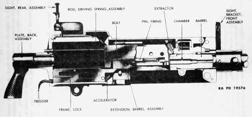
Figure12 - M1919A4 Machine Gun -- Right Side Sectional View
d. The compressed driving spring at this moment expands and forces the boltassembly forward. As the bolt assembly now travels forward, the barrel extensionis released from the lock frame, and the barrel plunger spring, which wascompreaed during the recoil motion, returns the barrel extension and barrel intofiring position. Meanwhile, the bolt has been locked to the barrel extension andthe barrel The firing pin is then released and strikes the contact point of thecartridge case. As the firing pin strikes the cartridge, another cycle isstarted, and succeeding cycles will continue as long as ammunition is suppliedand trigger action is maintained.
a. The following description exempUfies the cyclic operations of amanually-exerted trigger-activated cal. 30 Browning machine gun (fig. 12).This functional description is identical with that of trigger bar, solenoid, ortrigger motor except for the actual manner in which the firing pin is released.NOTE: The ground guns are fired by direct action of the trigger camming the seardown to disengaPe it from the firing pin. The trigger of the MZ Aircraft Gun(Aexible) acts upon a triBBer bar which presses up on the seer holder, which inturn cama the seer laterally to release the firing pin. The solenoids or tri8Bermotor act upon the seer directly to move it laterally.
b. Every cycle of the gun entails certain simultaneous movements or partsfunctions which must be performed in perfect relationship. In order that thesefunctions be more fully explained, it ie deemed advisable that they receiveindividual treatment. These phases will be discussed in the following order:firing, recoiling, counterrecoiling, cocking, automatic firing, feeding,extraction and ejection.
(1) FIRING.
(a) With the gun loaded and the firing pin spring cocked, the gun is readyfor firing (fig.13).
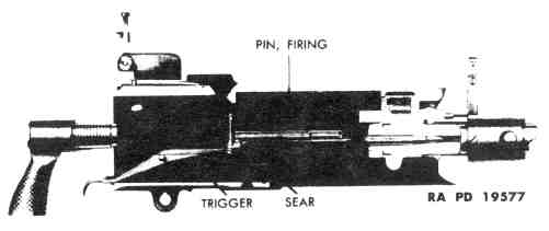
Figure13 - Ready To Fire Position
(b) Upon the action of the trigger, the trigger cams on the front end engagewith the came on the seer and force the tear down against the action of the searspring until the shoulder of the firing pin is released from the sear notch (fig. 14).The Firing pin is then driven forward through the bolt by the firing pin spring,and the firing pin contact point strikes and fires the cartridge
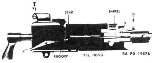
Figure14 - Firing Position
(2) RECOILING.
(a) The cycle of recoiling takes place as the cartridge is fired and thebullet is propelled from the end of the barrel (fig. 15).This causes a recoil stroke of the barrel, barrel extension, and the bolt. Thesegroups of parts are commonly called the recoiling parts.
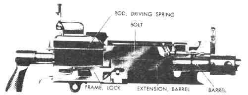
Figure15 - Recoiling Parts in Forward Motion
(b) At the time of firing, the breech lock is holding the bolt securelyagainst the cartridge and barrel (fig. 16),locking the barrel extension to the bolt. The breech lock is held in the lockedposition by the breech lock cam.
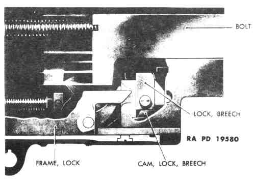
Figure16 - Breach Lock in Locked Position
(c) When the cartridge explodes and the bullet is propelled from the harrel,the force of the recoil drives the recoiling parts rearward. Within the firstpart of the stroke the breech lock drops off the breech lock cam and releasesthe bolt from the barrel extension. The breech lock itself is forced down by thefront projections of the lock frame acting on the breech lock pin. This takesplace when the recoiling parts have traveled approximately three-eighths inchrearward (fig. 17).Thus the holt is then free to continue its travel to the rear.
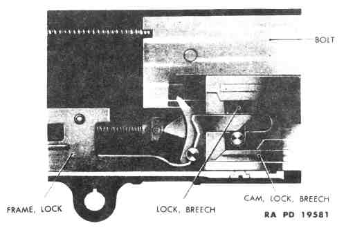
Figure17 - Breach Lock in Unlocked Position
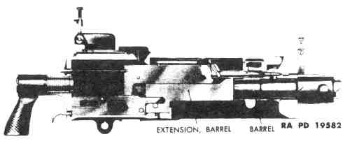
Figure18 - Recoiling of Barrel and Barrel Extension
(d) As the barrel extension moves rearward (fig. 18),the barrel plunger spring is compressed and the rear of the barrel extensionstrikes the accelerator and turns it backward. As the accelerator turnsbackward, its tips strike the bottom projections on the bolt and accelerate itto the rear At the same time the claws of the accelerator engage the shoulder ofthe T-lug on the barrel extension, locking it to the lock frame The acceleratorstop limits the backward motion of the accelerator. The barrel plunger spring isthus held compressed (fig. 19).
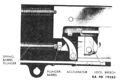
Figure19 - Barrel Plunger and Spring Compressed
(e) As the bolt is now paring freely in a rearward direction, the drivingspring is being compressed. Meanwhile the boh has, by means of the extractorsecured a fresh cartridge from the feed belt. The empty cartridge case is stillheld in the bolt T-slot.
(f) As the holt moves rearward, the upper portion of the cocking lever isforced forward in the cocking lever recess. The lower end, moving rearward,retracts the firing pin, thus compressing the firing pin spring against the searspring pin. The shoulder of the firing pin engages the notch in the sear whichis pulled upward by the sear spring The trigger cams are now disengaged from thesear.
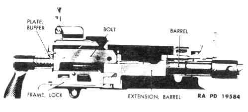
Figure20 - Recoil Completed
(1) The driving spring has been compressed and recoil completed (fig. 20)when the rear of the bolt strikes the buffer plate. The remaining rearward forceis absorbed in the buffer plate and the buffer disks. A part of the recoilenergy of the bolt is now stored in the driving spring assembly.
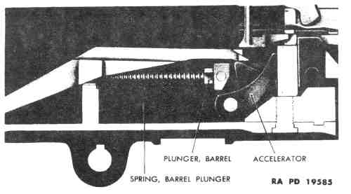
Figure21 - Barrel Plunger and Spring Released
(3) COUNTERRECOILING
(a) After completion of the recoil stroke, the bolt is propelled forward bymeans of the energy which has been stored in the driving spring and thecompressed buffer disks. When the bolt moves forward, the accelerator is struckby the projection on the bottom of the bolt. This rolls the accelerator forwardand releases the barrel plunger spring (fig. 21).(b) As the accelerator rolls forward, the accelerator claws are moved awayfrom the shoulders of the barrel extension shank, Thus the barrel extension isfree to move forward. This forward movement is accomplished by means of theexpansion of the barrel plunger spring, assisted by the forward motion of thebolt acting upon the accelerator.
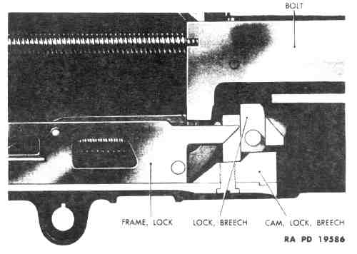
Figure22 - Breach Lock Engaged
(c) As the barrel extension moves forward, the breech lock engages the breechlock cam and is forced upward. The bolt, which has been continuing its forwardmotion since striking the accelerator has at this instant arrived at a positionwhere the notch on the under side is directly above the breech lock, thus thebreech lock engages the bolt (fig. 22),and the bolt is thereby locked to the barrel extension, and hence the barrel,just before the recoding parts reach the firing position.
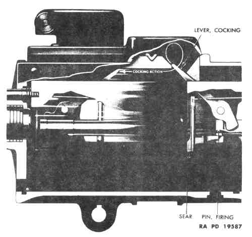
Figure23 - Cocking Action During Recoil
(4) COCKING.
(a) The act of cocking the gun is begun at the bolt moves in recoil. Theupper end of the cocking lever is forced forward by en- gaging the top plate (fig. 23)or the top plate bracket which is attached to the top plate of the M2 AircraftGuns This brings the lower end of the cocking lever to the rear.
(b) As the lower end of the cocking lever moves to the rear, it brings withit the firing pin. Thus the firing pin is withdrawn from the face of the boltand the firing pin spring is compressed against the sear spring pin.
(c) As the bob moves in counterrecoil, the upper end of the cock- ing leveris again engaged by the top plate, This remover the lower end from the path ofthe firing pin The pin is ready to strike when it is released from the sear.
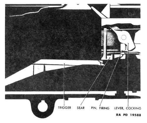
Figure24 - Automatic Firing
(5) AUTOMATIC FIRING.
(a) Automatic firing is accomplished by pulling the trigger which depressesthe front end, and then holding it thus in a firing position (fig. 24).The sear is depressed when its camming surface engages cam surfaces of thetrigger during the forward movement of the bolt near the end of thecounterrecoil stroke Depression of the sear releases the firing pin from thenotch at the bottom of the sear. The firing pin is then driven forward by theexpanding firing pin spring and automatically fires the next cartridge at theend of the forward stroke.
(b) The weapon will continue to fire automatically, at long as the trigger isheld in a firing position, until the supply of ammunition fed to the gun isexhausted.
Figure 25 - Action of Belt FeedMechanism
No Image Available
(6) FEEDING.
(a) The belt feed mechanism is actuated by the bolt (fig. 25).When the bolt is in its forward position, the belt feed slide is within theconfines of the gun. The lug on the end of the belt feed lever is engaged in thediagonal cam groove in the top of the bolt.
Figure 26 - Action of Belt FeedPawl
No Image Available
(b) As the bolt moves rearward during recoil, the belt feed lever is actuatedso that the forward end of the belt feed lever moves the belt feed slide out ofthe side of the casing and over the ammunition belt where the belt feed pawlthen engages the next cartridge for feeding into the feedway (fig. 26).The ground guns are fed from the left side. NOTE: The M2 Aircraft Gun isadaptable for feeding from either right or left side.
(c) As the bolt moves forward in counterrecoil, the belt feed lever isfurther actuated by the cam groove in the top of the bolt, so that the belt feedslide and the belt feed pawl are moved laterally.
(d) The belt feed pawl then carries the first cartridge against the cartridgestops. This new round is thus ready to be gripped by the extractor.
(e) The next cartridge is carried over the belt holding pawl which risesbehind it and holds it in position to be engaged by the belt fed pawl in thenext cycle.
Figure 27 - Extracting Cartridgeat Beginning of Recoil
No Image Available
Figure 28 - Beginning of BreachLock Unlocking
No Image Available
Figure 29 - Cartridge EnteringT-slot
No Image Available
Figure 30 - Ejecting FiredCartridge Case
No Image Available
Figure 31 - ChamberingCartridge
No Image Available